Road Bike Wheelsets vs. Mountain Bike Wheelsets How to Choose the Right Wheelset for Your Riding Terrain
The right wheelset determines your riding experience—whether you're gliding along smooth asphalt or conquering rugged mountain trails. Road bike wheelsets and mountain bike wheelsets are designed for different terrains, and the wrong choice can affect speed, stability, and safety. This guide will detail their key differences and help you choose the perfect wheelset for your riding style.
While road bike wheelsets and mountain bike wheelsets share a similar basic structure, their design, materials, and manufacturing processes are optimized for different terrains. Here are their differences:
1. Terrain Focus and Design Philosophy
Road Bike Wheelsets: Built for speed and efficiency on paved surfaces (city roads, highways, and racetracks). Aerodynamics, lightweight design, and low rolling resistance are primary considerations. Our road bike wheelsets, from carbon clincher tires to tubeless compatible models, feature narrow rims and streamlined designs to effectively reduce wind resistance and maximize the efficiency of each pedal stroke. Mountain Bike Wheelsets: Designed for durability and grip on rugged terrain such as mountain trails, gravel roads, mud, and rocky surfaces. Impact resistance and stability are our top priorities. Our mountain bike wheelsets feature wide rims for large off-road tires and utilize reinforced carbon fiber construction and tubeless tire optimization to effectively prevent punctures and easily handle jumps and off-road impacts.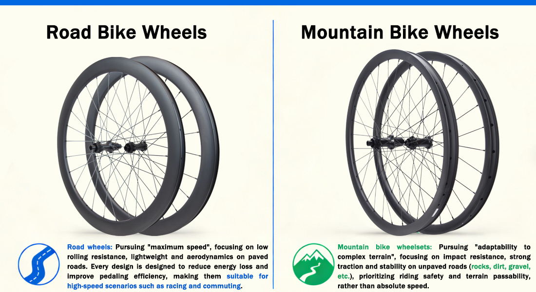
2. Key Feature Comparison
- Weight: Road bike wheelsets (1300-1800 g/set) are ultralight, offering excellent acceleration and climbing performance—our carbon fiber wheelsets take weight control to a whole new level. Mountain bike wheelsets (1800-2500 g and above) feature reinforced rims, thick spokes, and robust hubs for enhanced off-road durability.
- Aerodynamics: Road bike wheelsets, especially our deep-rim carbon fiber clincher wheelsets (30-88 mm), minimize wind resistance. Mountain bike wheelsets use shallow rims and wide spokes to improve stability, as aerodynamics is relatively less important in mountain biking.
- Spoke count and strength: Road bike wheelsets (18-24 spokes) prioritize lightweight design; Mountain bike wheelsets (28-36 spokes) feature robust hubs and spokes to evenly distribute stress and effectively absorb rock impacts.
- Tire compatibility: Road bike wheelsets are paired with narrow, slick tires (23-28c) to reduce rolling resistance. Mountain bike wheelsets are suitable for wide, treaded tires (2.1-2.8 inches) that provide good grip on soft surfaces.
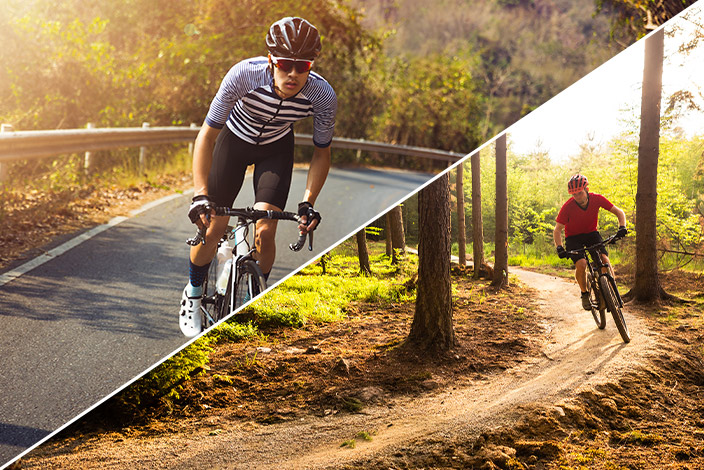
How to Choose Wheels Based on Your Riding Terrain
Choose the right wheels for your primary riding terrain—here's a targeted guide for our product range:
If you ride on the following terrains, choose road bike wheelsets:
1).Flat paved surfaces: Whether commuting, endurance riding, or climbing, our carbon fiber road bike wheelsets (tubeless or clincher) offer unparalleled speed and efficiency.
2).City streets: Lightweight road bike wheelsets are agile in traffic and can quickly cover longer distances—ideal for daily commutes.
3).Race tracks: Our aerodynamic carbon fiber wheelsets are designed to help competitive riders shorten race times and gain an advantage.
If you ride on the following terrains, choose mountain bike wheelsets:
1).Single tracks: Our reinforced mountain bike wheelsets provide stability and grip on tree roots, rocks, and technical sections.
2).Gravel and off-road: Tubeless mountain bike wheelsets offer puncture protection and a smooth ride even on rough, gravel surfaces.
3).Downhill and Freeride: High-strength mountain bike wheelsets with reinforced rims and durable hubs easily handle jumps, drops, and steep inclines.
3.Summary
There's no one-size-fits-all wheelset—road wheelsets are for road speed, while mountain bike wheelsets conquer off-road terrain. Choose the right wheelset for your riding style to achieve optimal performance.
Unsure which wheelset is right for you? Explore our range of carbon fiber road wheelsets and high-strength mountain bike wheelsets, or leave a message for consultation. Based on your terrain—we'll help you choose the perfect wheelset.